25+ data communication system block diagram
Used to store retain the data example SD card EEPROM DataFlash Real Time Clock etc. Business Process Diagram 23.
What Is The Difference Between Digital Communications And Digital Electronics And Communications And How Does The Scope Vary Quora
Fig 41 State Diagram Payroll Management 25.
. Vehicle Communication Interface Module VCIM OnStar 6. Programmable Logic Controllers continuously monitors the input values from various input sensing devices eg. Outside Rearview Mirror Switch.
A sensor communicatively coupled to or comprised in the device of the user may sense body activity of the user. A Block diagram of a memristive TRNG system for one-time password generation used for online payments. MicroController Interfacing Model Interfacing of an LED with 8051.
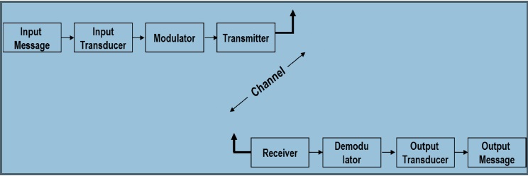
Basic Block Diagram of a Data Communication System Figure 3 shows the basic block diagram of a typical data communication system. It can be used to easily remove fuses from the fuse block. Data Link Connector DLC Heating Ventilation Air Conditioning.
Interfacing comprises of hardware Interface device and Software source code to communicate also called as the Driver. The source system. IO Pins up to 17 25 25 17 25 ContactLead Pitch 05 mm 05 mm 08 mm 065 mm 04 mm Dimensions 4x4x09 mm 5x5x1 mm 5x5x09 mm2 7x7x1 mm 82x53x20 mm 279x279x0482 mm Notes.
It is the building block of all object oriented software systems. Application Services Map View. There is a fuse puller located on the instrument panel fuse block.
Master will generate clock whenever it wants to write data to a Slave device. Payroll Management System 1519BEIT30052 25 Chapter 5 5. Human body activity associated with a task provided to a user may be used in a mining process of a cryptocurrency system.
They are modelled to capture the intended behavior of the system. Parallel data communication is expensive as well as very fast as its requires additional hardware and. The requirements of a system can be captured by Use Case Diagrams.
Payroll Management System 1519BEIT30052 24 DIAGRAM. Interaction modeling 51 Use Case Diagrams. In parallel data communication the data can be transferred through multiple cables at once.
This can further be broken down to three. Class Diagram The most widely use UML diagram is the class diagram. Body activity data may be generated.
For the sake of explanation I omitted Buffer Register. Data Base management System- solution By korth. A computer network is a set of computers sharing resources located on or provided by network nodesThe computers use common communication protocols over digital interconnections to communicate with each other.
After 8 clock pulses data in the master device A7 A0 is transferred to slave device and data in the slave device B7 B0 is transferred to the master device. Its a great starting point for any project discussion because you can easily identify the main actors involved and the main. Built with an advanced FPGA graphics processor the CN9950 offers better image and video quality to enhance the user.
The CN9950 KVM over IP Switch allows for remote access to video audio and virtual media of a PC or workstation and features DisplayPort high-definition video with resolutions of up to 4K DCI 4096 x 2160 30 Hz at both the local and remote consoles. AEC-Q100 Grade 1 Qualification is only offered for VQFN with wettable flanks and TQFP devices. DATABASE MANAGEMENT SYSTEMS SOLUTIONS MANUAL THIRD EDITION.
Video Rental System Data Flow Diagram. Linear block codes Convolutional codes and the state of the art turbo codes can be used to enhance the performance of the VLC system. A server may provide a task to a device of a user which is communicatively coupled to the server.
The polarization of memristive devices generates random fluctuations of some of its figures of merit eg set voltage set time state current which can be compared with a number to produce a string of zeros eg lower and ones ie. Data Base management System- solution By korth. It requires very less circuitry as well as wires.
These interconnections are made up of telecommunication network technologies based on physically wired optical and wireless radio-frequency. Download Free PDF View PDF. First of all the input bit stream is passed through the channel encoder optional.
Entity Relationship Diagram 25. A typical block diagram of PLC consists of five parts namely. Then the channel encoded bit.
Buffer SPI Communication Module Block Diagram. Thus this communication is very useful in compound circuits compared with parallel communication. The human immune system is composed of a distributed network of cells circulating throughout the body which must dynamically form physical associations and communicate using interactions between.
Accelerometer weight scale hardwired signals etc and produces corresponding output depending on the nature of production and industry. Class diagrams also help us identify relationship between different classes or objects. We use class diagrams to depict the static structure of a system by showing systems classestheir methods and attributes.
VQFN with wettable flanks. As the most known diagram type of the behavioral UML types Use case diagrams give a graphic overview of the actors involved in a system different functions needed by those actors and how these different functions interact. 12 shows the block diagram of the general physical layer implementation of the VLC system.
Use Case Diagram. Hospital Information System.

Block Diagram Of Communication System Information Source Gt Input Transducer Gt Transmitter Gt The Block Diagram Communication System Communication

Chapter 1 Signals And Spectra Digital Communications Fundamentals And Applications 3rd Edition Communications Fundamental Digital
What Is A Computer Block Diagram Quora
What Is A Computer Block Diagram Quora

Frequency Division Multiplexing Block Diagram Communication System Block Diagram Systems Engineering

8251 Is A Usart For Serialdatacommunication As A Peripheral Device Of A Microcomputer System The 8251 Receives Paralle Block Diagram Reading Writing Modem

Transmitter Receiver An Overview Sciencedirect Topics
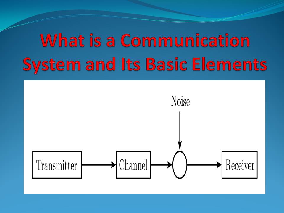
Communication System Basic Elements And Its Applications
![]()
Overview Of Wireless Pc Communication System Using Transceiver
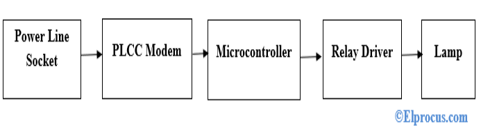
Power Line Carrier Communication Circuit Diagram And Its Working

Computer System Block Diagram With A Dma Controller And A Pic Computer Architecture Logic Design Engineering Design
What Is A Computer Block Diagram Quora
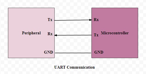
Basics Of Uart Explained Communication Protocol And Its Applications
![]()
Overview Of Wireless Pc Communication System Using Transceiver
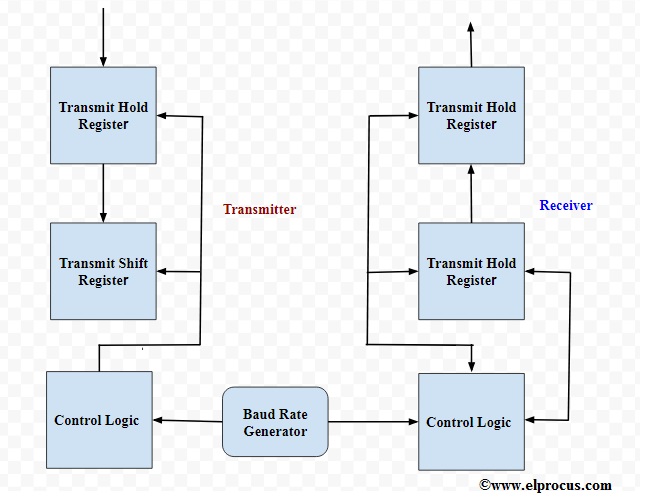
Basics Of Uart Explained Communication Protocol And Its Applications

Attiny85 Microcontroller Datasheet Pinout Specifications
Communication System Basic Elements And Its Applications